Unlike the eye, sensors based on silicon (including CCDs and CMOS sensors) have sensitivities extending into the near-infrared. Such sensors may extend to 1000 nm. There are a few DSLRs are capable of sensing infra red light, e.g. Fujifilm FinePix S3 Pro UVIR. However most of the digital cameras and video cameras are usually equipped with IR-blocking filters to prevent unnatural-looking images.
Objective: I am going to replace the built-in filters in front of the image sensor (CCD or CMOS) with an IR filter.
Such conversion will NOT yield special functions like thermographic imaging which wavelength range is about 9000 nm - 14000 nm. But it does pick up some light which can not be sensed by human eyes in the short wave infrared region.
Tools: 1. a right size screw driver; 2. a tweezer; 3. some lens paper; 4. some ethanol; 5. a dust blower; 6. solder kit (for certain models including 400D, 350D and earlier versions)
Here is my 5 years old Canon 400D for IR conversion.
You'll need to unscrew about 20-30 small screws, and unsolder the metal plate on the main circuit board. The camera is delicate and fragile, make sure your touches are gentle, especially while disconnecting the ribbon cables and dealing with the CCD sensor. All the process should be at least performed in a clean environment with minimal dust present.
The brief procedures are as below.
Camera Dissemble
 |
| Unscrew the bottom and side screws until you can open the back. |
 |
| Detach the big Ribbon cable and take the back (LCD display and control panel) away |
 |
| Unsolder the metal plate in order to access the bottom ribbon cable. (Be very careful and do not let your solder gun touch the cable or any components on the circuit board) |
 |
| Flip the main board over and you'll see the back of the CMOS assembly |
 |
Unscrew the necessary screws. Flip the CMOS assembly over. In front of the CMOS sensor, there are actually a series of optical component, including the IR blocking filters that I want to replace.
Here is a closer look of the CMOS sensor assembly.
In front of the imaging sensor, there are 1. Low-pass filter 1 that separates image in horizontal direction; 2. dichroic mirror and glass filter to pass only visible light from 400 nm to 700 nm; 3. Phaser layer (a quarter wave plate) to converts linear polarized light into circular; 4. Low-pass filter 2 that separates image in vertical direction.
Notes: The piezoelectric element is used for dust cleaning; the Low-pass filter 2 is attached on CMOS sensor as a protective window, I'll just leave it there.
CMOS sensor assembly layout
|
 |
| The CMOS sensor is dissembled from the assembly, leaving only the filters in front of it. |
 |
| CMOS without filter |
 |
| Back of CMOS |
 |
| The Low pass filter 1 and dichroic mirror (the two are attached together) can be taken off. This part will not be put back in the re-assembling process. |
 |
| Leaving only the glass filter on the supporting frame |
 |
| The sides of the glass filter is attached on the frame by tape |
 |
| Cut the tape |
 |
| Apply some force and push the glass filter off from the frame. The sides are glued on the frame, but one can easily push it off. (put a lens paper between the finger and filter) |
I now get rid of the IR blocking filters. You can screw everything back, that will give you a full spectrum camera. However since here I'd like to make an IR camera. I'll put my customized IR filter in.
Choice of IR filters:
There are many choices of IR filters in the market. Instead of purchasing a $200+ glass IR filter, here I considered some cheap ways to make a usable filter.
1. Developed Kodak negative film
I learned from the web that the developed negative film can be used as a IR filter. I bought the film from Walmart for ~$3, exposed it under sun light for 3-5 seconds and have it developed in Costco for free. My transmission measurement of the developed film is shown as blue curve in the figure below. As you can see the developed film still passes some light at 400 nm and 600 nm.
2. LEE Filters 3x3" Infra Red #87 Polyester Filter
I bought it from B&H for ~$14, the LEE filter is much better at rejecting visible light as can be seen from the red curve below.
Given the measured spectral transmission curves, LEE filter seems to be a much better choice than the exposed film.
In order to minimize the problem of focusing, (i.e., matching the refractive index of the IR filter to the original filter) I glued the sides of the IR LEE filter to a clean microscope slide. (I broke the slide to make it similar size with the IR blocking glass filter.) That gives me more or less the same optical path compared with the original filter.
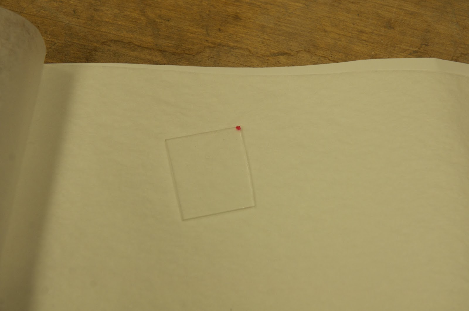
A piece of micro slide
 |
| Infrared LEE filter |
 |
| The LEE filter is glued on the glass slide |
Put the customized IR filter back into the frame. Put everything back in the reverse order of the dissembling process. The two things should not be put back are the dichroic mirror (and Low pass filter 1 of course since they are bonded together) and the green glass filter.